UJT relaxation oscillator (Sweep circuit with UJT switch)
Construction of UJT relaxation oscillator
The sweep circuit can be obtained with the help of unijunction transistor (UJT). The capacitor (C) start charging through the resistor (R) till the capacitor reaches the maximum voltage level VP, when the supply voltage VBB is ON. VP is known as the peak point voltage at this voltage UJT is turns ON. The capacitor (C) discharge rapidly through the resistance R1. The unijunction transistor turns OFF and allow the capacitor to charge again, when the capacitor voltage drops to a level VV. The Vv is called as valley point voltage.

Working Operation of UJT relaxation oscillator
The collector voltage (VC) and the base1 voltage waveform during the capacitor charging and discharging interval is shown in fig 2. The voltage is produced at the end of the base 1 in the form of narrow pulses called as trigger pulses. Similar pulses are generated at the base 2 terminal of the unijunction transistor (UJT) with the opposite polarity. The time constant RC and the type of UJT that is being used in the circuit set the period of oscillation or sweep period. But the period of oscillation or sweep period is does not depend on the supply voltage VCC and the temperature.

waveforms of UJT relaxation oscillator
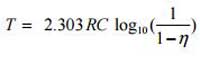
Sweep period expression,
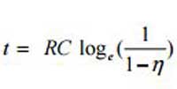
The value of sweep period is approximately equal to the ratio of peak point voltage to the supply voltage are,
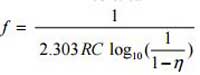
The sweep frequency is, the frequency of oscillation is the reciprocal of sweep period,