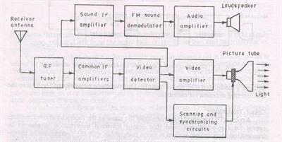

The color tv receiver consist of five section namely
- Radio Frequency (RF) Tuner
- Video Section
- PAL decoder / Color Processing section
- Synch Section
- Sound Section
RF TUNER
It consists of VHF (Very High Frequency) and UHF (Ultra High Frequency). It selects the desired T.V Channel and provides constant values of PIF = 38.9 MHZ and SIF = 33.4 MHZ.
Video Section
It consist of video detector which provides composite colour video signal (CCVS).This CCVS consist of pure video, synch pulses, colour signals, colour bus, AGC bias is also obtained from this section.
PAL Decoder / Color Processing section
It consist of colour demodulator which provides demodulated U and V signals. PAL decoder provides R.G.B signals.
Where,
R- Red
G-Green
B-Blue
Which are applied to picture tube and PAL decoder also consist of ACC (Automatic ColourControl ) and colour killer circuit.
Synchronization Section
This section provides horizontal and vertical synchronize pulses. It also provides colour bus which is used as trigger signal to generate CSC ( Colour Sub carrier ) signal. The horizontal and vertical pulses are applied to deflection coils of PT (Picture tube).The horizontal signal is also used to generate EHT (Extra high tension) supply of about 25 Kv.
Sound section
The output of FM (Frequency Modulator) detector is processed and the audio signal is reproduced by the speaker.