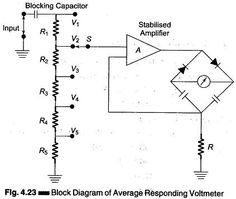

The basic construction of average responding voltmeter is shown in above fig. at the input side of an unknown voltage to be measured is applied. The blocking capacitor is used to block dc signals entering into the amplifier. A high stabilized amplifier is used to provide the amplification action. One terminal of high stabilized amplifier is connected to the attenuator network. This attenuator network is constructed by using five resistors R1 to R5. The other terminal of high stabilized amplifier is connected to the feedback path. The DC milliammeter is used as indicating meter. This meter is calibrated in terms of rms value. This meter is connected in the bridge circuit. The bridge circuit consists of two diodes and two capacitors.