Block diagram of instrumentation system
It is branch of engineering which deals with various types of instrument to record, monitor, indicate and control various physical parameters such as pressure, temperature, etc.
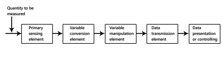
Block diagram of instrumentation system
The block diagram shown above is of basic instrumentation system. It consist of primary sensing element, variable manipulation element, data transmission element and data presentation element.
Primary sensing element
The primary sensing element is also known as sensor. Basically transducers are used as a primary sensing element. Here, the physical quantity (such as temperature, pressure etc.) are sensed and then converted into analogues signal.
Variable conversion element
It converts the output of primary sensing element into suitable form without changing information. Basically these are secondary transducers.
Variable manipulation element
The output of transducer may be electrical signal i.e. voltage, current or other electrical parameter. Here, manipulation means change in numerical value of signal. This element is used to convert the signal into suitable range.
Data transmission element
Sometimes it is not possible to give direct read out of the quality at a particular place (Example – Measurement of temperature in the furnace). In such a case, the data should transfer from one place to another place through channel which is known as data transmission element. Typically transmission path are pneumatic pipe, electrical cable and radio links. When radio link is used, the electronic instrumentation system is called as telemetry system.
Data presentation or controlling element
Finally the output is recorded or given to the controller to perform action. It performs different functions like indicating, recording or controlling.

