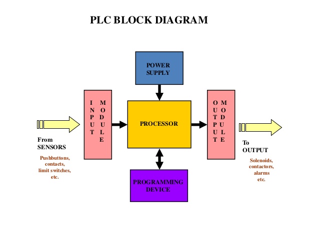
Block diagram of programmable logic controller (PLC)
The block diagram of programming logic controller (PLC) is shown in above figure. The PLC has following basic sections are,
- Processor section (CPU)
The processor section is brain of PLC which consists of RAM, ROM, logic solver and user memory. The central processing unit is heart of PLC. CPU controls monitors and supervises all operation within PLC. The CPU makes decision and executes control instructions based on the program instruction in memory.
- Input and output module
The input module is a mediator between input devices and central processing unit (CPU) which is used to convert analog signal into digital signal.
The output module is a mediator between output devices and central processing unit (CPU) which is convert digital signal into analog signal.
- Power supply
Power supply is provided to the processor unit, input and output module unit. Power supply may be integral or separately mounted unit. Most of the PLC operates on 0 volts DC and 24 volts.
- Memory section
The memory section is the area of the CPU in which data and information is stored and retrieved. Data Memory is used to store numerical data required in math calculation, bar code data etc. User memory contains user’s application program.
- Programming device
Programming devices are dedicated devices used for loading the user program into the program memory or edit it and to monitor the execution of the program of the PLC. It is also used to troubleshoot the PLC ladder logic program. Hand held terminal (HHT) or dedicated terminal or personal computer are programming devices commonly used in most of the PLCs.


