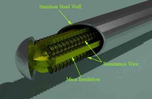
Resistance temperature detector (RTD)
The thermometer in which the resistance of conductor changes with change in temperature is known as resistance thermometer. The resistance thermometer is also called as resistance temperature detector (RTD).
Construction:
The resistance temperature detector (RTD) consists of a wire of metal wounded on grooved hollow insulating ceramic former which covered with protective cement. The ends of the coils are welded to stiff copper leads that are taken out to be connected in one of the arm of Wheatstone bridge circuit. The protective metal sheath is used to provide rigidity and mechanical strength.
Working:
As the temperature increases, the sensing materials sense it then the resistance of temperature detector is changed with changed in temperature. The RTD shows positive temperature coefficient (PTC) that is the resistance of RTD increases with increase in temperature. The resistance material should have a continuous and stable relation with temperature as given below.
R1 = R0 (1 + αt1)
If temperature changes from t1 to t2, then above equation becomes,
R2 = R1 (1 + α (t2 – t1))
Where,
R1 = Temperature at t1.
R2 = Temperature at t2.
α = Temperature coefficient of material.
R0 = Temperature at 0 degree Celsius.
The variation of resistance of sensing element is normally measured by using Wheatstone bridge.


