Power Factor Correction
Capacitive Power Factor correction is applied to circuits which include induction motors as a means of reducing the inductive component of the current and thereby reduce the losses in the supply. There should be no effect on the operation of the motor itself.
An induction motor draws current from the supply, that is made up of resistive components and inductive components.
The resistive components are:
- Load current
- Loss current
The inductive components are:
- Le akage reactance
- Magnetizing current
The current due to the leakage reactance is dependant on the total current drawn by the motor, but the magnetizing current is independent of the load on the motor.
The magnetizing current will typically be between 20% and 60% of the rated full load current of the motor. The magnetizing current is the current that establishes the flux in the iron and is very necessary if the motor is going to operate.
The magnetizing current does not actually contribute to the actual work output of the motor. It is the catalyst that allows the motor to work properly. The magnetizing current and the leakage reactance can be considered passenger components of current that will not affect the power drawn by the motor, but will contribute to the power dissipated in the supply and distribution system.
Take for example a motor with a current draw of 100 Amps and a power factor of 0.75 The resistive component of the current is 75 Amps and this is what the KWh meter measures. The higher current will result in an increase in the distribution losses of (100 x 100) /(75 x 75) = 1.777 or a 78% increase in the supply losses.
In the interest of reducing the losses in the distribution system, power factor correction is added to neutralize a portion of the magnetizing current of the motor.
Typically, the corrected power factor will be 0.92 – 0.95 Some power retailers offer incentives for operating with a power factor of better than 0.9, while others penalize consumers with a poor power factor. There are many ways that this is mete red, but the net result is that in order to reduce wasted energy in the distribution system, the consumer will be encouraged to apply power factor correction.
Power factor correction is achieved by the addition of capacitors in parallel with the connected motor circuits and can be applied at the starter, or applied at the switchboard or distribution panel. The resulting capacitive current is leading current and is used to cancel the lagging inductive current flowing from the supply.
Methods of Power Factor Correction
Capacitors connected at each starter and controlled by each starter is known as “Static Power Factor Correction” while capacitors connected at a distribution board and controlled independently from the individual starters is known as “Bulk Correction”.
Bulk Correction
The Power factor of the total current supplied to the distribution board is monitored by a controller which then switches capacitor banks In a fashion to maintain a power factor better than a preset limit. (Typically 0.95)
Ideally, the power factor should be as close to unity (Power factor of “1”) as possible. There is no problem with bulk correction operating at unity.

Capacitor banks
Static Correction
As a large proportion of the inductive or lagging current on the supply is due to the magnetizing current of induction motors, it is easy to correct each individual motor by connecting the correction capacitors to the motor starters.
With static correction, it is important that the capacitive current is less than the inductive magnetizing current of the induction motor.
In many installations employing static power factor correction, the correction capacitors are connected directly in parallel with the motor windings. When the motor is off-line, the capacitors are also off-line. When the motor is connected to the supply, the capacitors are also connected providing correction at all times that the motor is connected to the supply. This removes the requirement for any expensive power factor monitoring and control equipment.
In this situation, the capacitors remain connected to the motor terminals as the motor slows down. An induction motor, while connected to the supply, is driven by a rotating magnetic field in the stator which induces current into the rotor.
When the motor is disconnected from the supply, there is for a period of time, a magnetic field associated with the rotor. As the motor decelerates, it generates voltage out its terminals at a frequency which is related to it’s speed.
The capacitors connected across the motor terminals, form a resonant circuit with the motor inductance.
If the motor is critically corrected, (corrected to a power factor of 1.0) the inductive reactance equals the capacitive reactance at the line frequency and therefore the resonant frequency is equal to the line frequency.
If the motor is over corrected, the resonant frequency will be below the line frequency.
If the frequency of the voltage generated by the decelerating motor passes throu gh the resonant frequency of the corrected motor, there will be high currents and voltages around the motor/capacitor circuit. This can result in sever damage to the capacitors and motor. It is imperative that motors are never over corrected or critically corrected when static correction is employed.
Static power factor correction should provide capacitive current equal to 80% of the magnetizing current, which is essentially the open shaft current of the motor.
The magnetizing current for induction motors can vary considerably. Typically, magnetizing currents for large two pole machines can be as low as 20% of the rated current of the motor while smaller low speed motors can have a magnetizing current as high as 60% of the rated full load current of the motor.
It is not practical to use a “Standard table” for the correction of induction motors giving optimum correction on all motors. Tables result in under correction on most motors but can result in over correction in some cases. Where the open shaft current can not be measured, and the magnetizing current is not quoted, an approximate level for the maximum correction that can be applied can be calculated from the half load characteristics of the motor.
It is dangerous to base correction on the full load characteristics of the motor as in some cases, motors can exhibit a high leakage reactance and correction to 0.95 at full load will result in over correction under no load, or disconnected conditions.

Power Factor Correction
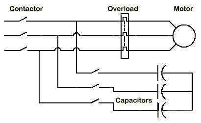
Static correction is commonly applied by using one contactor to control both the motor and the capacitors. It is better practice to use two contactors, one for the motor and one for the capacitors. Where one contactor is employed, it should be up sized for the capacitive load. The use of a second contactor eliminates the problems of resonance between the motor and the capacitors.