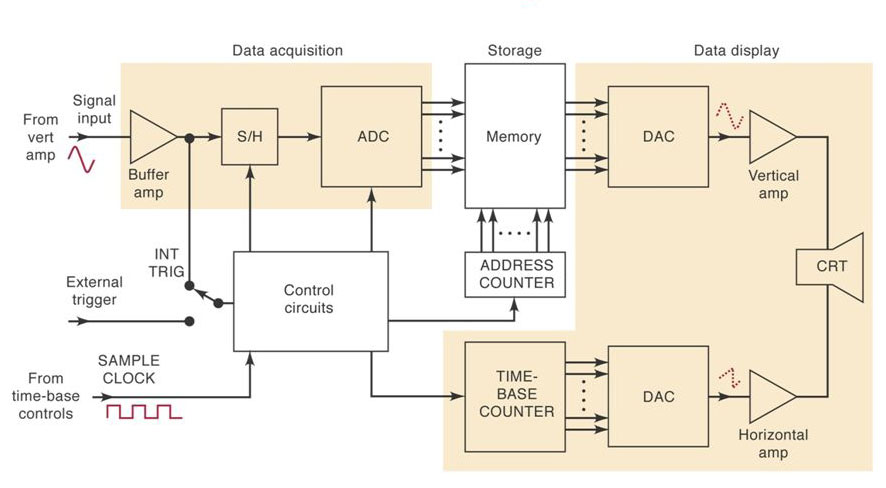
Block diagram of digital storage oscilloscope
The block diagram of digital storage oscilloscope is shown in above figure. In this method, the waveform to be stored is digitized, stored in a digital memory and retrived for display on the storage oscilloscope. The stored waveform is continuously displayed by repeatedly scanning the stored waveform and a conventional CRO tube can be used for the display. The stored display can be displayed indefinitely as long as power is applied to the memory, which can be supplied with a small battery. The input is amplified and attenuated with input amplifiers.
The output of the input signal amplifiers feeds an analog to digital converter (ADC). There are numbers of ADC available. But the selection of ADC is depends on the speed of converters, because the conversation of analog to digital signal should be in fast rate. A digital storage oscilloscope digitizes the input signal, so that all subsequent signals are digital. The storage occurs in electronic digital memory.
The input signal is digitized and stored in memory in digital form. In this state it is capable of being analyzed to produce a variety of different information. To view the display on the CRT, the data from memory is reconstructed in analog form. Digitizing occurs by taking a sample of the input waveform at periodic intervals. In order to ensure that no information is lost, the sampling rate must be at least twice as fast as the highest frequency in input signal. If this is not done then aliasing will result.
This requirement for a high sampling rate means that the digitizer must have fast conversion rate. Hence requires flash analog to digital converters, whose resolution decreases as the sampling rate is increased. Hence bandwidth and resolution of a digital oscilloscope depends on analog to digital converters.


