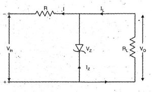
Zener diode as a voltage regulator
When the zener diode is operated in reverse biased condition at breakdown voltage, the reverse resistance drops to a very low value and the effort of a rapid resistance in zener current together with a rapid decrease in resistance produces a constant voltage across the zener diode.
Operating principle
Above figure shows the circuit of zener regulator where the zener diode is connected in parallel with the load due to this a zener regulator is also known as shunt voltage regulator. Zener voltage VZ of zener diode is reverse connected across the unregulated DC voltage VI. To limit the zener current, the resistor RS is connected in series with the zener diode which is also called series current limiting resistor. The output voltage VO is taken across the load resistor.
For a better operation, the input voltage must be greater than the zener voltage. The zener diode is operates in reverse breakdown condition. The unregulated input applied to the zener diode. If these input voltages go beyond the zener voltage then the zener diode operates in reverse breakdown region and maintains a constant VZ=VO voltage across the load in spite of input AC voltage fluctuations or load current variations. The input current is given by
The input current IS is the sum of zener current and load current.
IS = IZ + IL OR IZ = IS – IL
When the load current increase the zener current decreases so that the input current remains constant. The output voltage is given by according to Kirchhoff’s voltage law are,
VO = Vi – IS RS
The output voltage is remaining constant as the input current is constant. This circuit is also correct for the changes in input voltage. When the input voltage increase, more zener current will be flow through the zener diode which increase the input voltage and the voltage drop across the resistor RS but it will remain constant the load voltage.


