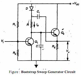
How bootstrap sweep circuit is work?
The circuit diagram of bootstrap sweep is shown in above figure. In the bootstrap sweep circuits the transistor Q1 acts as a switch and Q2 as an emitter follower or a unity gain amplifier. The capacitor C1 is charged to VCC through the diode forward resistance RE when transistor Q1 is ON and transistor Q2 is OFF. Simultaneously the output voltage VO is zero. When a negative pulse is applied to the base of the transistor Q1, it is turned OFF. The output voltage VO is the same as the base voltage of Q2, as the transistor Q2 as an emitter follower. If Q1 is turned OFF, capacitor C1 starts charging capacitor C through the resistor R. Because of this, the base voltage of Q2 and the output voltage begin to rise above zero. As this output voltage increases, the diode D gets reversed biased. This is because the output voltage is coupled through capacitor C1 to the diode. As the capacitor C1 has value much greater than that of capacitor C, the voltage across capacitor C1 virtually remains constant. Hence, the voltage drop across resistor RC also remains constant. In view of this, the current IR through RC also remains constant. This means that capacitor C is charged with a constant current. In view of this, the voltage across capacitor C and hence, the output voltage is made to increase linearly with time. It may be since that the circuit pulls itself up by its own bootstrap. Because of this the circuit is called as bootstrap sweep circuits. When the negative pulse is removed from the input of the transistor Q1 then the capacitor C is discharge rapidly through Q1 and the output voltages is returns to zero. Now the capacitor C1 is again gets charged to voltage VCC through diode D.


