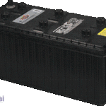


Posted inElectronics Articles
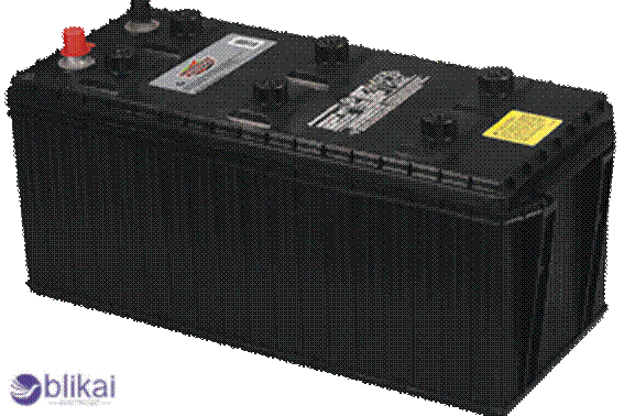
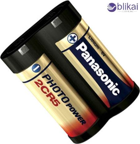
Is Duracell 245 the Same as 2CR5?
In the case of specialty batteries, such an occurrence is not a rarity to experience in the quantity of similar-sounding products. The Duracell 245 and the 2CR5, two naming systems…